An overview of how to set up internet failover for an office or home lab.
We started working out of our Infraspec office last year. To start with we had a broadband connection from ACT. It worked fine till it didn’t. One fine day, few people on call started complaining that their calls were getting dropped. On checking, we found that our internet went down. We raised a complaint and but nothing would get fixed immediately.
This incident got us to think more about our internet reliability. We also have our internal workloads running on Raspberry PIs, so it is important for us to get
reliable internet connectivity to run efficiently.
This led to get another internet connection(Airtel) which we can use as a backup connection. Now we have got two wireless connections, If one goes down we can just manually switch to another.
However, this does require some manual effort.
We needed a cost-effective way where if the primary connection(which is ACT for our case due to high network bandwidth) goes down, it could auto-switch (or failover)
to the secondary backup connection(Airtel) and restores back to the primary connection once it regains its connectivity. This led to think about failover/multi-WAN
setup.
Overview
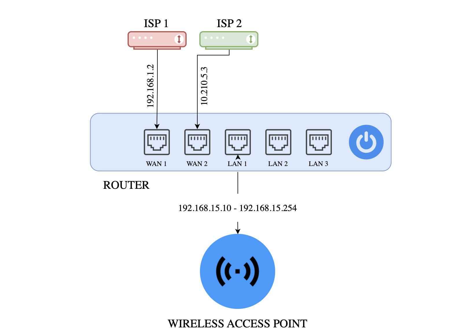
- Two ISP connections (primary and secondary)
- Failover setup (not load balancing)
- Quick switching time between ISPs
- Clients should be part of a single network (IPs allocated from a single DHCP server)
Context
Few routers provide the flexibility to configure individual Ethernet ports. By default, out of all the available ports, either one/two is configured as the WAN port and the others are configured as LAN ports. This allows you to connect your WAN connection to the WAN ports and use the remaining LAN ports to connect devices on your office network. You can also configure the Ethernet ports in different ways, such as configuring multiple ports as WAN ports for a multi-WAN setup.
This would allow you to connect a second Internet source, such as a second broadband modem to the router and use it as a redundant WAN connection. You can then configure the router to use both WAN connections and switch between them if one of the connections fails. This can help to provide a more reliable and resilient Internet connection for your Office/Home lab.
Note: Not all routers allow the conversion of LAN ports to WAN ports. If your router does not have this option, you will need to use a different router or a network switch to create a WAN port. Some routers also come equipped with multiple WAN ports that can be used as well for failover in case one of the connections fails.
How we go about setting up the internet failover
The process to set up internet failover may vary depending on our specific setup and needs, but generally, we will need to follow these steps:
- Identify the primary and secondary internet connections that you will use for failover. In our case, We are using ACT as our primary as I mentioned due to its high bandwidth and Airtel as our secondary connection.
- Configure your network router or network switch to use the primary internet connection as its default gateway.
- Configure the secondary internet connection as a backup gateway in your router or switch.
- Test the failover by disconnecting the primary internet connection and verifying that the secondary connection is used automatically.
The configurations to manage
We can manage router configurations by login to the router’s web-based configuration page. This can typically be done by entering
the router’s IP address (such as 192.168.1.1) in a web browser. The configurations will vary with the router you have, here we
will take an overview of the process we need to follow to manage the router’s configuration.
1. Configure WAN/LAN as a WAN port
- Our router had only one WAN port, We need to convert one of its LAN port to a WAN port as we need two internet sources.
- Once we have accessed the router’s configuration page, look for a section on bridging or port forwarding. From here,
you should be able to remove the port from the bridge by selecting the port and choosing the option to remove it.
Now this second port (eth2 in our case) can be used as another WAN port.
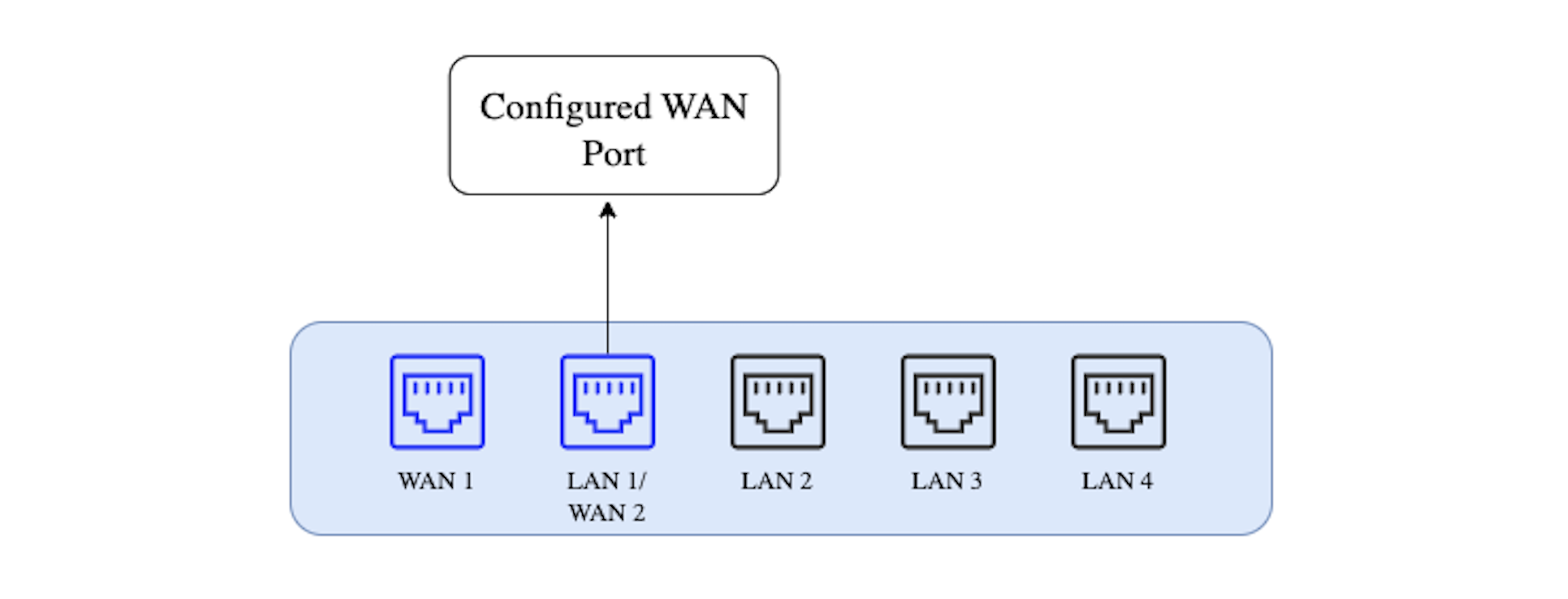
- By default, the LAN ports are configured as a single network, with all the ports being part of a single bridge.
Now that we have two WAN ports/interfaces (eth1 & eth2) ready to act as our internet sources, the next step is to configure DHCP Clients for these ports.
2. Setup DHCP client
- Plug in the ISP cables to both the WAN interfaces we just configured in the above step.
- In the network settings, We need to enable the DHCP client and configure the network settings.
- After the DHCP client has been configured, the device should be able to automatically obtain an IP address from the DHCP server on the network.
Each ISP has its own DHCP server, the router acts as a DHCP client for each ISP connection. This would allow the router to obtain IP address information from each ISP and use that information to route traffic appropriately. This blog is written considering dynamic IP assignments only.
3. Configure routes
- Now we need to configure the routes for our primary and the secondary internet connection, For that find the settings for the routing table, which is typically found in the advanced settings or network settings section of the router’s configuration page.
- Check the default configured static routes, else create two default routes for the primary and the secondary internet connection. Then configure the gateway address and WAN interface to it.
- Then we need to specify the route distance for each WAN connection by assigning a value to each WAN connection. The lower the value, the higher the priority of the connection. For example, if you have two WAN connections, you might assign a value of “1” to the primary connection and a value of “2” to the secondary connection. This will ensure that the primary connection is used whenever possible, and the secondary connection is only used if the primary connection is unavailable.
4. Setting up the DHCP Server
- We need to have uninterrupted connection for all our devices in the office network. Instead of using the ISP’s DHCP servers (both will provide different IPs from different pools), we will be setting up our own DHCP server which will be providing IPs from a single IP pool.
- This DHCP server will be assigning IPs to all the devices connected to the LAN bridge. Till now all the connections are wired, and we need to provide a wireless access point to which the clients (devices) will be able to connect wireless. The Access Point is connected to one of the LAN ports and since it is part of the bridge network, all the devices connected via access point will be assigned the IP from our DHCP server instead of ISPs.
5. Testing our setup
- Although there are a lot of tools available to simulate network failures, we chose a simpler approach to test the working of our setup.
- Router provides us with the capability to disable the physical ethernet interfaces. To simulate the network failure on the primary ISP, we disabled the ethernet port. Within a few seconds, we should see the secondary/ failover connection kick in and the internet traffic flowing through it.
- Once we enable the primary connection port again, we should see that the traffic again is directed through the primary ISP.
Conclusion
In this article, We had an overview on how to go about setting up the office/home lab internet failover connection. We discussed configuring
WAN interface, setting and configuring the DHCP client and server, and finally we looked at testing our setup.
In the next part, We will set up the internet failover in MicroTik hex series router which is the one we have used at our office.


